|
|  |
| Notices |
Welcome to the sSnakeSs community. You are currently viewing our boards as a guest which gives you limited access to view most discussions and access our other features. By joining our free community you will have access to post topics, communicate privately with other members (PM), respond to polls, upload content and access many other special features. Registration is fast, simple and absolutely free so please, join our community today! If you have any problems with the registration process or your account login, please contact contact us.
|
 01-07-05, 11:34 PM
|
#1
|
|
Member
Join Date: Oct-2004
Location: London, Ontario
Age: 39
Posts: 856
|
Wiring a Dimmer
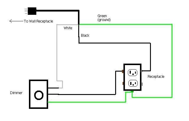
I'm preparing to wire up a dimmer using this link as my reference from the "How To" post.
http://www.ssnakess.com/forums/showt...&threadid=8858
I am a bit confused as to which wire goes where. I made a wiring diagram to help me understand and I need you guys to confirm it for me so I know what to do when I actually wire it all up. Any help will be very much appreciated!
|

|
|
|
01-08-05, 12:26 AM
|
#2
|
|
Member
Join Date: Mar-2003
Location: Ontario Canada
Age: 65
Posts: 1,485
|
That will work, but put the dimmer in the live side not the neutral. In other words just switch the black and white wires... Black is live, white is neutral. Also the output of the dimmer, will then go to the short prong of the receptacle, just the reverse of what you illustrate.
The green wire is illustrated correctly and is your ground wire and not normally a current carrier. Its there for your protection just in case a live part of the circuit touches the metal electrical box, in which case you'll blow a fuse rather than create a shock hazard.
One further note on dimmers. The cheaper dimmers under 10 bucks, will usually not restart if they are turned down low. In even a short power failure you'll find they don't come back on until you first turn them up, then down to your normal level. This causes lots of herpers grief when they find their animals cold after even a short power blip
You can avoid this by purchasing the more expensive dimmers in the 15 to 25 buck range.
It's not always easy to tell which ones employ the better circuit, but look for terms like "full range dimming"
It's very easy to test for. Simply turn them down low, and unplug them , then plug them in again a couple times.. Test to see if you still have heat without readjusting them.
Another tip, is to always put a small neon type pilot light across the output . You can either just tie it across the receptacle or put it across your heat tape(in parallel) Make sure the pilot light is rated for 120VAC. Radio Shack and any electronic component store will have these.
This will allow you a visual feedback that your dimmer is working. The brightness of the light will go up and down with the dimmer level..
__________________
Uncle Roy
-----------------------------------------
Herpetology - more than a hobby
It's a Lifestyle
celebrating 26 years of herp breeding
|
|
|
|
|
01-08-05, 12:39 AM
|
#3
|
|
Please Email Boots
Join Date: Mar-2007
Posts: 1,867
|
Very good answer Roy, you really summed it up.
I was thinking, maybe he has worked for a company like I have, who decided to ignore standards and use white as the hot, and black as a neutral.
"we are a huge company, let's ignore the standard, and pick colors by a role of the dice - and then pretend we are right"
Very confusing and sometimes dangerous for many contract electricians. What was worse, was they decided to switch back at one point, and only the older stuff was wired that way - the newer stuff was wired normally.
Ryan
|
|
|
|
|
01-08-05, 01:04 AM
|
#4
|
|
Member
Join Date: Oct-2004
Location: London, Ontario
Age: 39
Posts: 856
|
That was an impressive reply Roy! I appreciate all your tips. I will be using your pilot light idea for sure and will be on the lookout for "full range dimming" when i buy a dimmer.
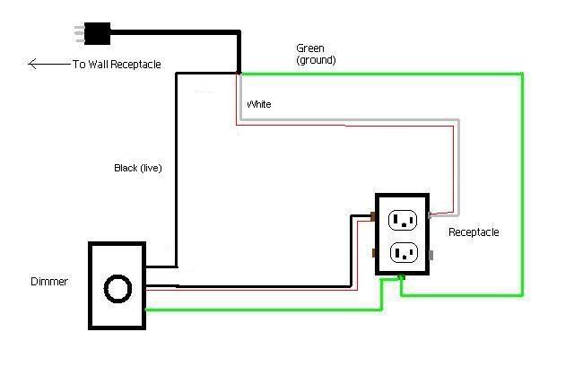
So to finalize things I have edited my previous diagram. The red line is where I can make a break in the wire and attach a light or just tie it across the receptacle as you stated. Thanks for your help!
|
|
|
|
|
01-08-05, 03:20 AM
|
#5
|
|
Member
Join Date: Mar-2003
Location: Ontario Canada
Age: 65
Posts: 1,485
|
You shouldn't have to break the wires. Simply run the pilot light off the two unused screws of the receptacle. If you want to remote the pilot light further from the box, you can use lamp cord to run it to wherever you want.
There is even a superior way of utilizing the pilot light to actually tell you your heat tape is working and not just the dimmer.
Attach the light across the far end of the heat tape, the side at the end of the run , or the opposite end of where you attach the supply from the dimmer.
This means the current that feeds the light has passed through the heat tape connections and along the entire length of the internal bus wires. So an illuminated light not only means your dimmer is working, it also means that continuity exists right through your heat tape connections
__________________
Uncle Roy
-----------------------------------------
Herpetology - more than a hobby
It's a Lifestyle
celebrating 26 years of herp breeding
|
|
|
|
|
01-08-05, 09:50 AM
|
#6
|
|
Member
Join Date: Aug-2003
Location: Stony Plain
Posts: 40
|
Excelent , if I can add something to that is use a filament bulb for an indicating light. It is a high current device and will not be fooled by smaller gate currents in electronic devices.
|
|
|
|
|
01-08-05, 11:59 AM
|
#7
|
|
Member
Join Date: Mar-2003
Location: Ontario Canada
Age: 65
Posts: 1,485
|
You can use small night light bulbs if you prefer ,But filament bulbs burn out. Neons last for over a decade and that is why I prefer them. LED's can also be used with suitable diodes and limiting resisitors, but I find they don't have enough variation in brilliance to be very good dimmer indicators.
Peter what you're referring to, is the fact that neons will illuminate as the result of snubber circuits used for noise suppresion in triac output circuits. This is because they drawm next to no current, so leakage current around and through solid state thyristors can produce a glow.
This however wont be a problem provided a heating load is also on the circuit.
I've been using Neons across dimmer outputs for decades and they work adequately, but they won't illuminate all the way down to off.. They will stop producing light about 1/4 revolution of the dimmer, but that is no big deal.
I've actually built analog meter movement type displays for monitoring heat tape,but that is more involved.
__________________
Uncle Roy
-----------------------------------------
Herpetology - more than a hobby
It's a Lifestyle
celebrating 26 years of herp breeding
|
|
|
|
|
01-08-05, 08:43 PM
|
#8
|
|
Member
Join Date: Oct-2004
Location: London, Ontario
Age: 39
Posts: 856
|
Thanks for all the help! I will probably be assembling it on Monday. One final question:
Can I replace the receptacle with a power bar instead?
|
|
|
|
|
01-08-05, 11:06 PM
|
#9
|
|
Member
Join Date: Mar-2003
Location: Ontario Canada
Age: 65
Posts: 1,485
|
Certainly, but you should make all terminations inside a metal switch box rather than having dimmers just hanging by wires.
If you buy a power bar get at least a six foot one and cut the cord off somewhere in the middle leaving enough length to run both the receptacle and plug ends into an electrical switch box to make the connections. Use Marrette twist on wire nuts.
Also mount the dimmer in the switch box, and get the suitable cover plate for the dimmer.You'll probably end up with a slide dimmer and they need a plate with a large rectangular hole.
Use clamp type strain reliefs, the metal ones and put one on each side of the box, by pushing out two of the 7/8" knockouts. That way the cord entering and leaving the box is supported.
__________________
Uncle Roy
-----------------------------------------
Herpetology - more than a hobby
It's a Lifestyle
celebrating 26 years of herp breeding
|
|
|
|
|
01-09-05, 12:07 AM
|
#11
|
|
Please Email Boots
Join Date: Mar-2007
Posts: 1,867
|
Quote:
Originally posted by Stockwell
.... neons will illuminate as the result of snubber circuits used for noise suppresion in triac output circuits. This is because they drawm next to no current, so leakage current around and through solid state thyristors can produce a glow.
|
Well obviously.
But doesn't the thyristor suppression have a synergistic relationsiship with the triac outputs, in a bilatial fortitude complex, and therefore, any diodes used in the circuit should be sodomized?
Just something from 3rd semester electronics that I remember, I think 
Ryan
|
|
|
|
|
01-09-05, 09:09 AM
|
#12
|
|
Member
Join Date: Aug-2003
Location: Stony Plain
Posts: 40
|
We could debate the best way to do this for a long time. A diac -triac circuit may work very well with neon light. A transistor output circuit will not. The more expensive dimmer switches that don't have a lantern effect may have a transistor/scr output so I would use a filament bulb. Also if the bulb burns out you can consider it as" fail safe".
Last edited by Peter Ludwig; 01-09-05 at 09:19 AM..
|
|
|
|
|
01-09-05, 05:13 PM
|
#13
|
|
Member
Join Date: Jan-2005
Location: okotoks
Age: 38
Posts: 20
|
i dong get it. my heat wave only has 2 prongs that i plug into the wall. that means that i am only going to have a black wire and a white wire. does that mean i totaly overlook the green wire. and just hook up the black and the white.
__________________
zoom zoom
|
|
|
|
|
01-09-05, 06:36 PM
|
#14
|
|
Member
Join Date: Jan-2005
Location: okotoks
Age: 38
Posts: 20
|
iv done alot of electrical in cars and if its anything like a car i could probly do it. in a car it is battery to switch and then switch to the thing ur trying to power. is it the same in a house. outlet to dimmer then dimmer to heat pad. and cant i jsut use the cut off end of the plug and plug it into the outlet and attact the constant power to the dimmer then have the positive from the dimmer of the the heat pad. then the negitive from the plug in go to the dimmer and then attach the ngitive from the heat pad to the dimmer also. that should ground it out right. does this make sence
__________________
zoom zoom
|
|
|
|
|
01-10-05, 06:03 AM
|
#15
|
|
Member
Join Date: Aug-2003
Location: Stony Plain
Posts: 40
|
A few years ago many appliances were made of conductive material and a safety ground had to be used to shield the user from being the only path to ground if the hot was to touch the appliance casing. Now a days almost all appliances are made of plastics and/or are double insulated therefore not requiring a safety ground. Also notice now all two prong plugs are polarized. When wiring up your circuits the big prong is the neutral and the small prong is the hot. DC and ac circuits are very different. House circuits are tied to the ground and your water system so be careful when working with them.
|
|
|
|
 Posting Rules
|
You may not post new threads
You may not post replies
You may not post attachments
You may not edit your posts
HTML code is Off
|
|
|
All times are GMT -6. The time now is 01:30 PM.
Powered by vBulletin®
©2000 - 2025, Jelsoft Enterprises Ltd.

Copyright © 2002-2023, Hobby Solutions.
|
 |


 Linear Mode
